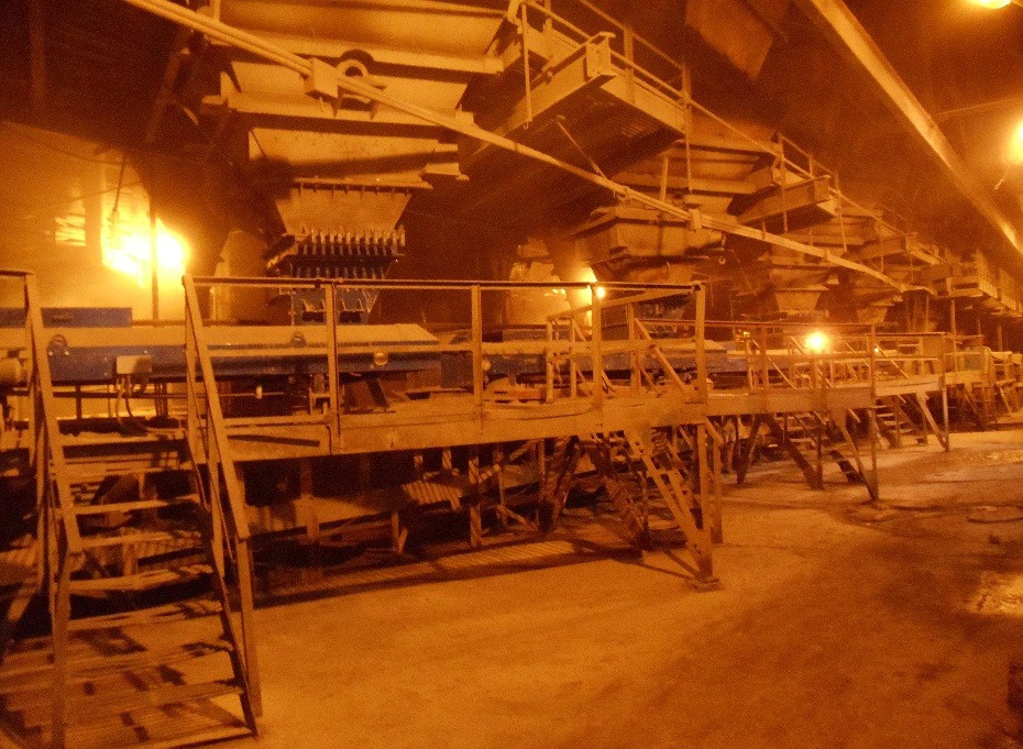
In sinter production, that uses the processing of various bulk materials, quite often there are problems of materials hanging in hoppers, chutes, on guiding trays and other objects. Hanging leads to a disruption in the normal technological process of production, a decrease in the labor productivity, a decrease in the quality and volume of products.
One of the main tasks in sinter production is to ensure the uninterrupted operation of the charge department, on which the productivity of the sinter plant largely depends. The charge is a multicomponent bulk material, where composition must comply with technological standards. Violation of the dosing process and untimely supply of various components to the charge conveyor belt leads to a decrease in product quality, and in some cases to its rejection.
It is logical that the main requirement for hoppers is confined to unhindered unloading of material and its uninterrupted supply to the production process. Due to the increased humidity, lower temperatures, changes in the particle size distribution of bulk materials, as well as due to various design features of the hoppers and their physical condition, ore and other components in the hoppers often hang, forming arches and bridges that prevent the release of bulk materials from hoppers.
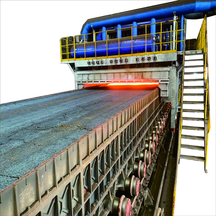
Problem of material hanging is usually handled in a rather primitive way, by means of poking through special holes or pockets, as well as lowering personnel into the hopper, that is fraught with great danger. This practice is contrary to all labour safety requirements. Sometimes sudden collapses of arches cover the pokers, up to fatal cases. Another example of the use of manual labour to force material out of a hopper is the use of sledgehammers or more powerful impact tools such as swinging rails.
Everyone knows the consequences of this method:
- deformed walls, where even more complex hangings of materials are formed,
- destroyed welded joints and bases of fastenings of the entire structure of the hopper,
- frequent injuries to service personnel.
In addition to the low efficiency of this method of arch collapsing, one has to face the frequent shutdowns of processing lines for unscheduled repairs.
Until recent times, the traditional mechanical systems for hanging elimination were electric vibrators and pneumatic impulse systems.
- Electric vibrators are short-lived, often lead to the destruction of the hoppers walls, to the compaction of the material in the hopper.
- Pneumatic systems require the generation and preparation (drying) of high pressure air, and are inefficient in case of material freezing.
Since the 1990s, to eliminate the hanging of bulk materials, electric vibrators and pneumatic systems have been replaced by efficient and economical in operation magnetic-impulse installations IM, having a number of advantages compared to their predecessors, namely:
- possibility of prompt adjustment of the amplitude, shape and repetition rate of the acting impulses;
- possibility of not only collapsing the suspended material, but also cleaning the surface (hopper wall) from adhering material;
- operation in an energy-saving mode with minimal operating costs;
- preservation of the integrity of the cleaned walls of hoppers and other surfaces;
- ease of operation, maintainability, durability. The service life of installations IM before overhaul is at least 10 years.
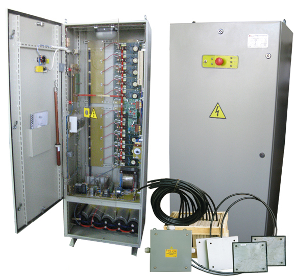
At present, a lot of IM magnetic-impulse installations have been implemented in the sinter production of various metallurgical plants:
- Arcelor Mittal (Kazakhstan, Temirtau; Ukraine, Kryvyi Rih; Czech Republic, Ostrava);
- U.S. Steel Kosice s.r.o (Slovakia, Kosice);
- ISD Dunaferr (Dunayváros, Hungary);
- “MK” Azovstal” (Ukraine, Mariupol);
- “Cherepovets MK” (Russian Federation, Cherepovets);
- “Ust-Kamenogorsk MC” (Kazakhstan, Ust-Kamenogorsk);
- Zaporizhstal (Ukraine, Zaporozhye);
- others (see the list of implementations).
Such objects are equipped with IM installations as:
- Hoppers for various purposes:
- reception;
- charge ones of sintering machines;
- charge dosing area with ore, concentrate, lime;
- limestone crushing area;
- intermediate;
- Loading, unloading units of drum mixers and pelletizers, various reloading chutes;
- Swash plates of loading trolleys (loading trays) of sintering machines;
- Dust collection hoppers for gas cleaning systems.
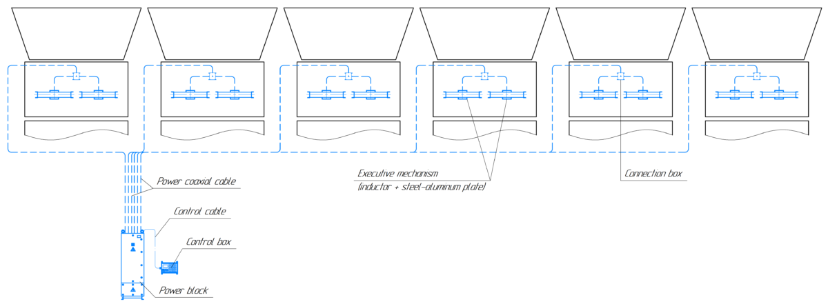
Examples of equipping schemes for various production facilities with IM installations
Receiving, dosing hoppers, and of sintering machines, with charge, ore, concentrate, limestone, lime and others (100 tons and more)
For these hoppers, installations of the type IM4-1,8-n, IM5-1,8-n are applicable, where n is the number of channels from 1 to 16, 2 executive mechanisms per channel.
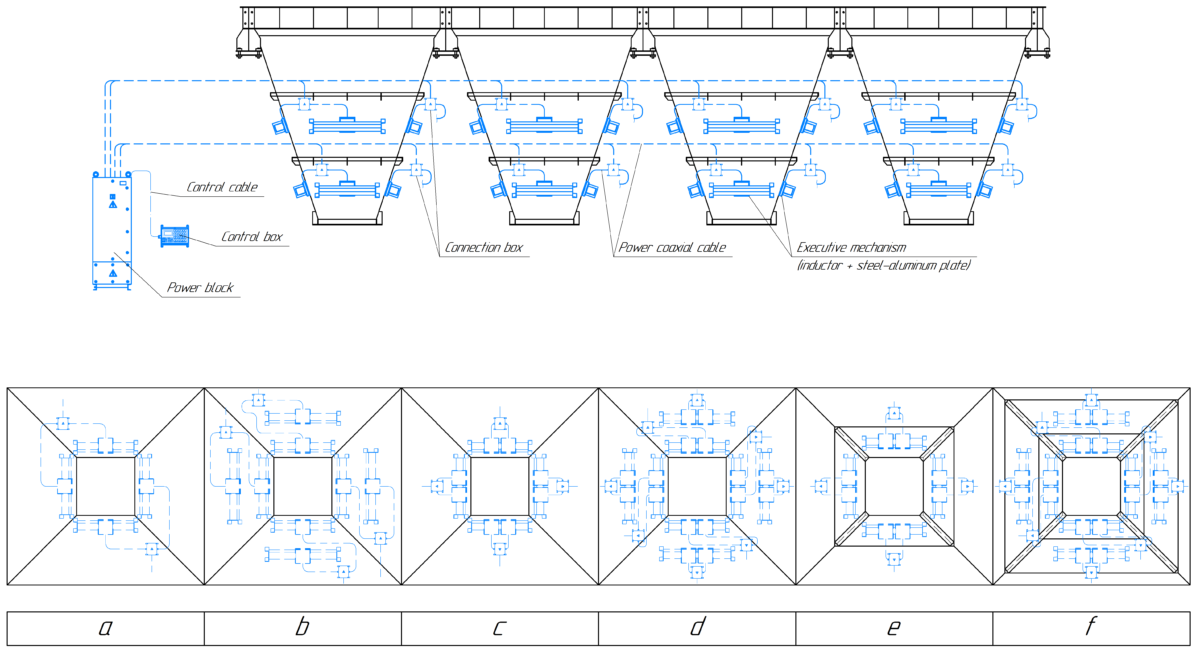
Rectangular hoppers, the inclined part of which has the shape of an inverted truncated pyramid
Options for placing executive mechanisms:
a – on the outer wall in one tier, one mechanism per edge;
b – on the outer wall in two tiers, two mechanisms per edge;
c – on the outer wall in one tier, two mechanisms per edge;
d – on the outer wall in two tiers, four mechanisms per edge;
e – on a vibrating sheet in one tier, one or two mechanisms per edge;
f – on a vibrating sheet in two tiers, two or four mechanisms per edge.
The number of executive mechanisms and their allocation over the surface of the hopper depends on its capacity, the thickness of the walls to be cleaned, the presence and design of stiffeners, physical and chemical properties, and humidity of the loaded bulk material.
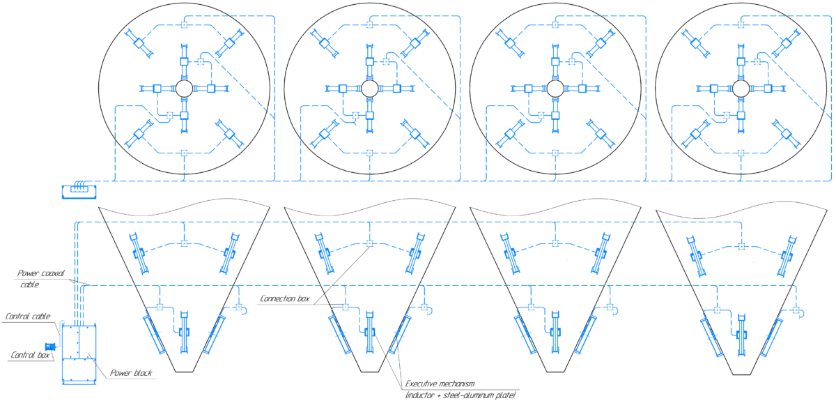
Cylindrical hoppers with a conical inclined part. Executive mechanisms are placed in one or two tiers
External view of the charge hopper of the sinter machine equipped with the installation IM
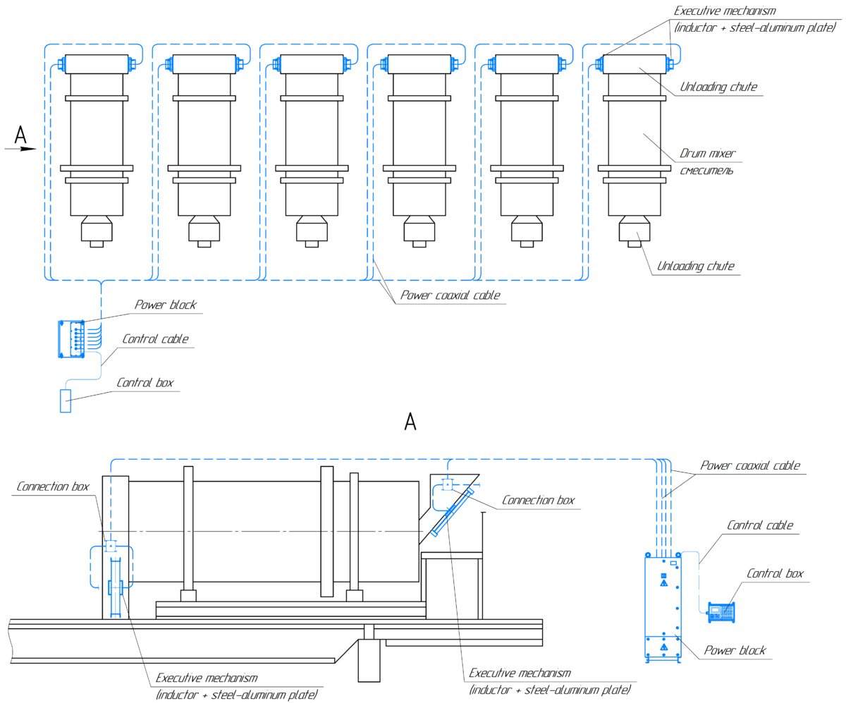
Loading and unloading chutes of secondary mixing drums
For these objects the installations of IM3-1,1-n, IM3-1,9-n type are applicable, where n is the number of channels from 1 to 16, two executive mechanisms per channel.
Placement of executive mechanisms on loading and unloading chutes of mixing drums – two mechanisms for each chute
Intermediate hoppers (interhoppers)
For these hoppers, installations of the type IM3-1,1-n, IM3-1,9-n, IM4-1,8-n, are applicable, where n is the number of channels, from 1 to 16, two executive mechanisms per channel.
Intermediate hoppers. Allocation of executive mechanisms – two for each industrial hopper
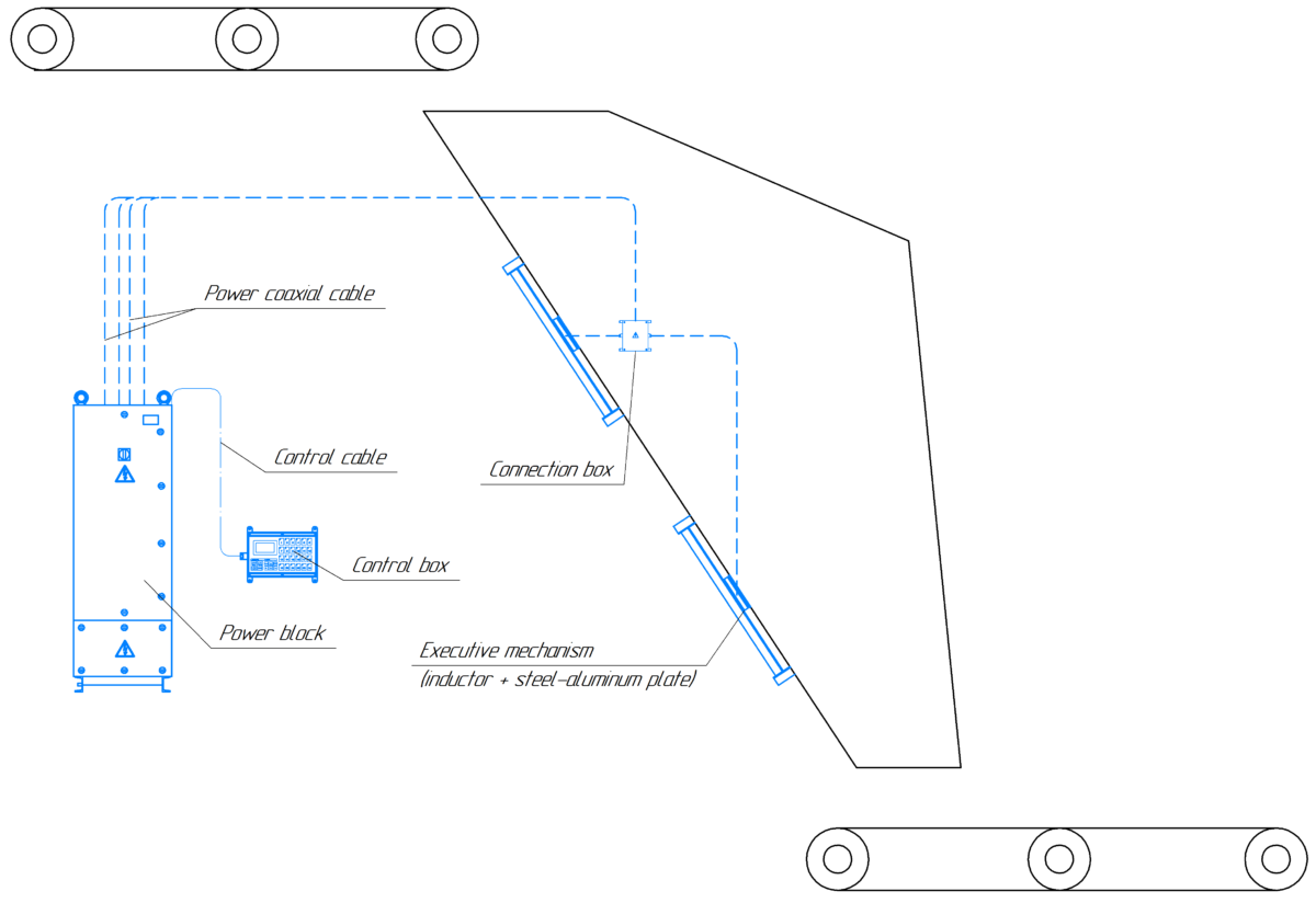
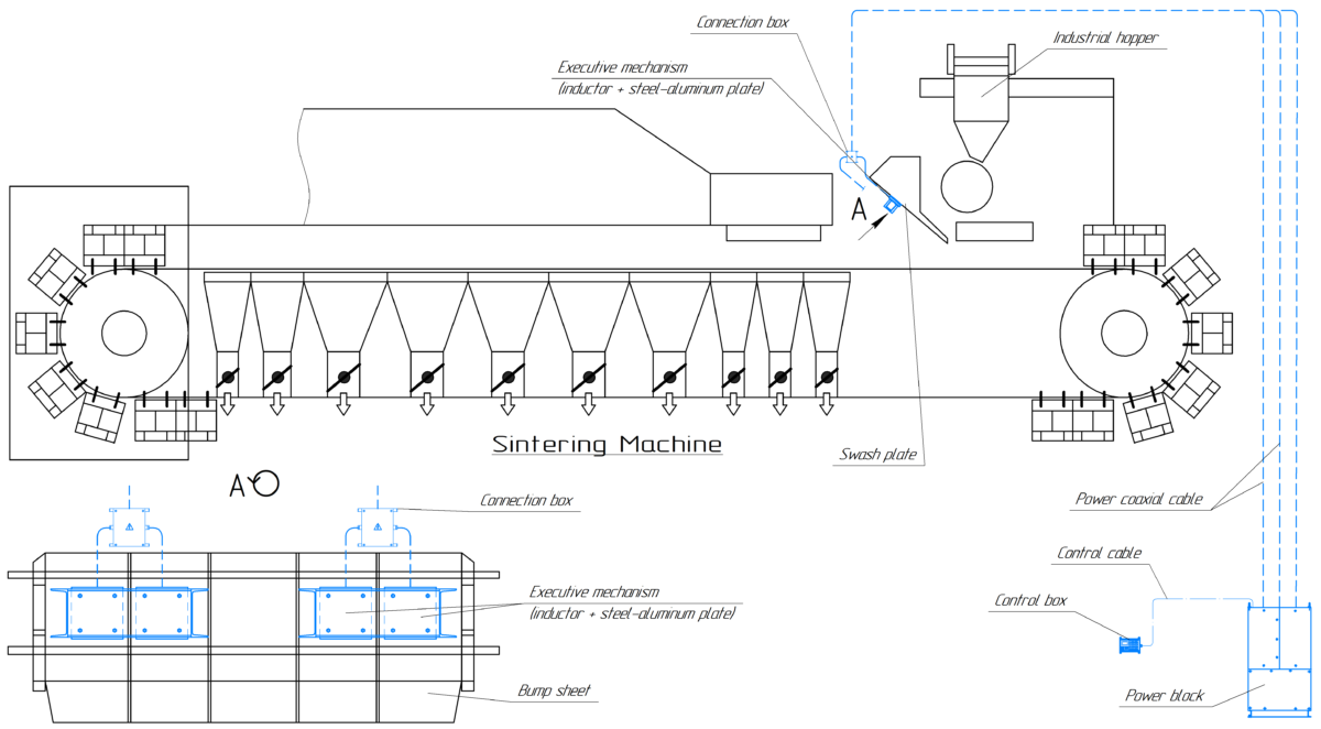
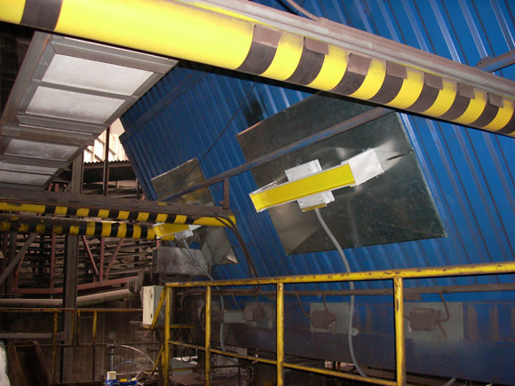
Surge plates for loading trolleys of sinter machines
For these hoppers, installations of the type IM3-1,1-n, IM3-1,9-n, IM4-1,8-n are applicable, where n is the number of channels, from 1 to 16, two executive mechanisms per channel.
The use of magnetic-impulse installations for cleaning the surge plates of loading trolleys of sintering machines
Dust collection hoppers for bag and electric precipitators, hoppers for the dust shipment section
Dust collection hoppers for electric and bag filters, as well as storage hoppers for the dust shipment section are equipped by installations IM. For these hoppers, installations of the type IM3-1,1-n, IM3-1,5-n are applicable, where n is the number of channels, from 1 to 16, two executive mechanisms per channel.
The example of allocation of executive mechanisms on dust collection hoppers in one tier
The external view of dust collection hoppers of electric precipitator of the sinter production, equipped by installation IM
Magnetic-impulse installations IM have proven to be a reliable tool for preventing materials from hanging, surpassing traditional pneumatic systems and electric vibrators in efficiency, simplicity and cost-effectiveness being in operation (see the reviews of NKGOK (ArcelorMittal Kryvyi Rih) #1, NKGOK (ArcelorMittal Kryvyi Rih) #2, Azovstal #2, Azovstal #3, Azovstal #5, Dnieper Metallurgical Combine, Alchevsk Iron and Steel Works, Yenakievo Metallurgical Plant).
In general, the installations IM replace previously used traditional systems. For example, at the sintering plant of metallurgical plant “Azovstal”, starting from 1993, hoppers and chutes have been equipped with magnetic-impulse systems based on installations IM. Up to the closure of the sinter plant in 2012, 12 installations IM were in operation there, and the use of electric vibrators was completely excluded.
At some enterprises, there is a joint operation of installations IM and traditional systems, while the latter are used as auxiliary equipment operating in sparing modes. For example, at OJSC Dnieper Metallutgical (Kamenskoye), after the introduction of installations IM on 12 charge hoppers of sintering machines, the previously operated pneumatic collapsing system was not dismantled, but continues to be used as an auxiliary system. The annual cost of the air consumed by the system has decreased, according to the calculations of 2006, by about UAH 300,000 (see review).
Implementation of installations IM on the hoppers of sintering machines and in front of the pelletizing drum in the sintering production of the U.S. Steel, s.r.o. Kosice allowed to reject the weekly blasting works to collapse the deposits of materials suspended in these hoppers.
At present moment, magnetic-impulse systems of arches collapsing based on installations IM are included in the projects for the reconstruction and construction of new sintering productions carried out by various design institutes.
MITEK carries out works on the further implementation of installations IM at various sinter production facilities.
Your orders are always welcome!
Implementations map
Magnetic-impulse installations IM:
- ensure a sustainable release of material from equipped hoppers;
- clean the walls of hoppers from adhered material;
- provide efficient filter regeneration;
- operation in an energy-saving mode, operating costs are minimal;
- basically do not require reconstruction of hoppers when equipping them;
- do not violate the integrity of the walls of the hoppers;
- compatible with strain gauge systems for controlling the weight of material in hoppers;
- comply with the requirements of the Directives and harmonized technical regulation of the European Union on electrical safety and electromagnetic compatibility;
- applicable in hazardous areas of class 22, hazardous by ignition of combustible dust in accordance with the ATEX Directive;
- easily integrated into modern automated process control systems;
- reliable and durable (according to technical conditions – 10 years, in practice, some installations have already been in operation for more than 25 years).

